8.6 The Sydney Opera House
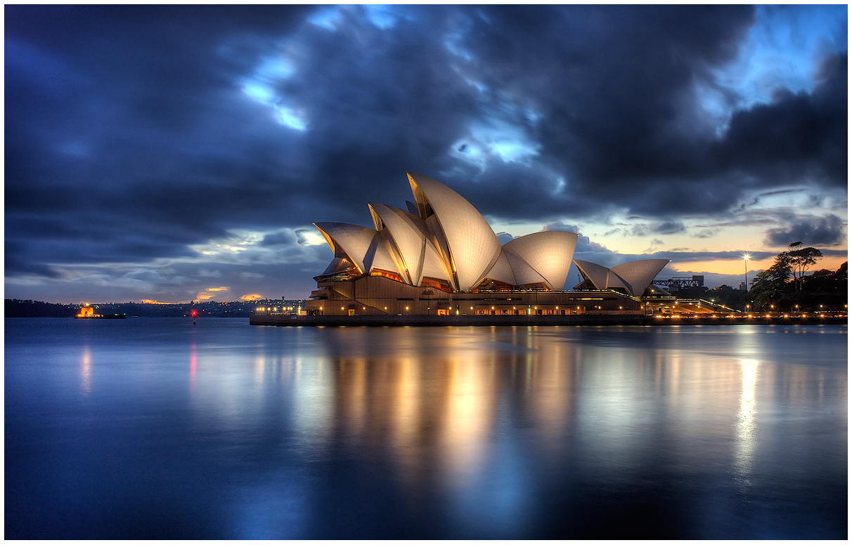
The Sydney Opera House resulted from an international competition launched in 1955 for the design of a building dedicated to performing arts. The winner, announced in 1957, was the project of Jørn Utzon, a Danish architect little known until then. His project, even though not fully satisfying the competition requirements, was selected by one of the jury members - the famous architect Eero Saarinen - that foreseen it as a landmark project. The proposal consisted in a set of shell-shaped roof structures, capable of accommodating various performance venues. The result of this final proposal is represented in this figure.
The Sydney Opera House. Photograph by Brent Pearson.
Clearly innovative, the Utzon’s design was too advanced for the design and construction technologies of the time and was by many considered impossible. In the three years that followed the start of the construction in 1959, Utzon, along with the structural engineering team of the Ove Arup company, tried to find a mathematical formulation for his hand-drawn shells. A variety of different approaches were experimented, including parabolic, circular and elliptical shapes, but all of the solutions had, besides enormous technical difficulties, very high costs that were completely incompatible with the approved budget.
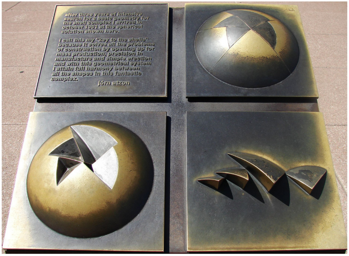
In the summer of 1961, Utzon was on the brink of despair and decided to dismantle the shells’ Perspex model. However, when stacking the shells for storage, he found that they fit almost perfectly inside each other, which would only be possible if the different shells had the same curvature at all its points. Incidentally, the surface that has the same curvature at all its points is the sphere, which led Utzon to think that maybe it would be possible to shape his shells as cut triangles from a sphere’s surface. Although this design was not exactly identical to the original drawings, it had the advantage of being calculable in computers and, more importantly, of allowing a more economic construction. Utzon’s idea is explained in a bronze model placed next to the building of the Opera House, as can be seen in this figure.
Bronze plaque explaining Utzon’s idea for modeling the shells. Photograph by Matt Prebble.
Unfortunately, construction delays and increasing costs led the government to question the political decision to build the Opera House and forced Utzon to resign when the construction of the interiors was not yet finished. Utzon was devastated and left Australia in 1966, never to return. Against the wishes of most architects, the building was completed under the responsibility of Peter Hall and inaugurated in 1973 without a single reference to Utzon. Unfortunately, the work of Peter Hall was not at the same level as Utzon’s and the contrast between the stunning exteriors and simple interiors led the work to be considered a "semi-masterpiece". Despite Utzon’s personal drama, this story turned out to have a happy ending: thirty years later, the Australian government remodeled the Sydney Opera House to reunite the masterpiece with its architect and got Utzon, who never got to see his work finished, to be engaged with the refurbishment, aiming to rearticulate the exterior with the interior.
In this section, we will model the shells of the Sydney Opera House following exactly the same solution proposed by Utzon. All the building shells will be modeled by spherical triangles obtained by three cuts in a sphere. This figure shows two spheres of equal radius from which we cut two triangles, in order to get two of the half-shells that constitute the Sydney Opera House.
Two of the half-shells that constitute the Sydney Opera House, and the spheres from where they were obtained by a succession of cuts.

To define the section planes that will cut the triangles we can consider that the building will be aligned in a direction parallel to the \(Y\) axis, so the shell’s symmetry axis will correspond to a section plane whose normal is the \(X\) axis, as can be seen in this figure. The two remaining section planes will have normals determined so as to approximate, as rigorously as we can, the volumes imagined by Utzon. As is also visible in this figure, the half-shells are extracted from spheres with equal radius but centered at different positions. Thus, to model these half-shells we are going to define a function that, from the center \(P\) of the sphere of radius \(r\) and the normals \(n_1\) and \(n_2\) of the section planes, produces a spherical shell with thickness \(t\) and with the desired shape.
Top view of two of the half-shells that constitute the Sydney Opera House, and the spheres from which they were obtained by a succession of cuts.

half_shell(p, r, t, n1, n2) =
move(slice(slice(slice(subtraction(sphere(u0(), r),
sphere(u0(), r-t)),
u0(),
n2),
u0(),
n1),
x(-p.x),
-vx()),
p-u0())
As an example, this figure shows a half-shell generated by evaluating the following expression:
half_shell(xyz(-45, 0, 0), 75, 2, vsph(1, 2.0, 4.6), vsph(1, 1.9, 2.6))
A half-shell of the Sydney Opera House.

To produce a complete shell, we only have to apply a reflection to the half-shell by the vertical section plane:
shell(p, r, t, n1, n2) = mirror(half_shell(p, r, t, n1, n2), u0(), -vx())
This figure shows the shell generated by evaluating the following expression:
shell(xyz(-45, 0, 0), 75, 2, vsph(1, 2.0, 4.6), vsph(1, 1.9, 2.6))
A Sydney Opera House shell.

To define a row of shells of the Opera House we will use values that approximate the produced shells with Utzon’s original drawing:
row_shells() =
union([shell(xyz(-45.01, 0.0, 0.0), 75, 2,
vsph(1, 1.9701, 4.5693), vsph(1, 1.9125, 2.5569)),
shell(xyz(-38.92, -13.41, -18.85), 75, 2,
vsph(1, 1.9314, 4.5902), vsph(1, 1.7495, 1.9984)),
shell(xyz(-38.69, -23.04, -29.89), 75, 2,
vsph(1, 1.9324, 4.3982), vsph(1, 1.5177, 1.9373)),
shell(xyz(-58.16, 81.63, -14.32), 75, 2,
vsph(1, 1.6921, 3.9828), vsph(1, 1.4156, 1.9618)),
shell(xyz(-32.0, 73.0, -5.0), 75, 2,
vsph(1, 0.91, 4.1888), vsph(1, 0.8727, 1.3439)),
shell(xyz(-33.0, 44.0, -20.0), 75, 2,
vsph(1, 1.27, 4.1015), vsph(1, 1.1554, 1.2217))])
Invoking this function will produce the row of shells presented in this figure.
A row of shells of the Sydney Opera House.

In order to facilitate the positioning of the building, we will include a rotation around the \(Z\) axis, a scaling, and a final translation applied to each row of shells. Since the building has two rows of shells, we will call this function half_opera_sydney:
half_opera_sydney(rot_z, sca, trans_x) =
move(scale(rotate(row_shells(), rot_z), sca),
vx(trans_x))
Finally, we can model the entire Opera House by making a row of shells at a scale of \(1.0\) and a second row of shells as a reduced, rotated and shifted version of the first. The scale used by Utzon was \(0.8\), and the rotation angles and the translations that we are going to use are those that allow us a higher resemblance to the actual building:
opera_sydney() =
begin
half_opera_sydney(0.1964, 1.0, 43)
half_opera_sydney(-0.1964, 0.8, -15)
end
The final result of modeling the shells of the Sydney Opera House is shown in this figure.
The complete model of shells of the Sydney Opera House.

8.6.1 Exercises 41
8.6.1.1 Question 158
Define a function that creates a link of a chain, such as the one shown on the left of the following image.

To simplify the modeling process, consider the link as decomposable into fourths of a link, as shown on the right of the previous image. This way, it will be enough to define a function that creates a fourth of a link (composed by a quarter of a torus and a cylinder), and then apply a double reflection in the \(X\) and \(Y\) axes to compose the complete link.
The function should receive, as parameters, the radius \(r_l\) of the link, the radius \(r_i\) of the wire, and the length \(l\) between the semi-circles, such as shown in the following scheme.

8.6.1.2 Question 159
Define a function capable of creating chains such as those presented below:

8.6.1.3 Question 160
Define a function to create closed chains such as the one presented below:

Note that the links suffer successive rotations around the \(X\) axis.